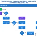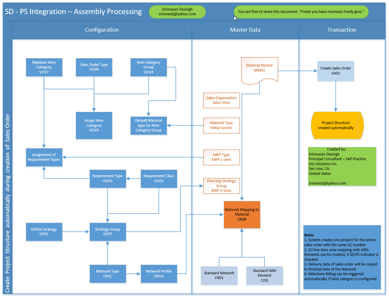
This visual illustrates the end-to-end SD–PS integration flow used for assembly processing in SAP. It explains how a sales order automatically triggers project creation and how configuration, master data, and transactional steps work together. The diagram helps readers understand which settings are required, how master data supports the flow, and how the project structure is generated during sales order processing.
Process Flow Description
The flowchart is divided into three main areas: Configuration, Master Data, and Transaction. Together, these areas show how assembly-related sales orders result in an automatically created project structure.
1. Configuration Area
This section shows the required SD and PS customizing steps that enable project creation during sales order entry.
- Sales Order Setup
- Maintain item category
- Define sales order type
- Assign item category to sales order type
- Assign requirement types and requirement classes
- Item Category and Requirements
- Item category group assignment
- Default material type for item category group
- Requirement type determination
- Requirement class assignment
- Strategy and Planning Integration
- Define planning strategy
- Assign strategy to strategy group
- Project System Configuration
- Define network types
- Define network profiles
These settings ensure that when a relevant sales order item is entered, SAP knows that a project structure must be created instead of a standard delivery-based process.
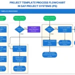
2. Master Data Area
This section highlights the master data objects that must be correctly maintained to support SD–PS integration.
- Material Master
- Sales view for SD processing
- Material type and initial setup
- MRP view for planning
- Planning strategy group assignment
- Project and Network References
- Standard network definition
- Standard WBS element
- Network mapping to material
The master data links materials used in sales orders to predefined project and network templates. This ensures consistent project structures for similar assembly products.
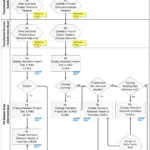
3. Transaction Area
This section shows the operational execution of the process.
- Sales Order Creation
- Sales order is created using the defined order type and item category
- Automatic Project Creation
- Project structure is generated automatically
- WBS elements and networks are created based on configuration and master data
No manual project creation is required. The system derives the project structure directly from the sales order.
Key Flow Logic
- Sales order entry is the trigger point.
- Item category and requirement type control whether PS integration is activated.
- Material master and planning strategy determine how the project is planned.
- Standard WBS and network templates ensure consistent project structures.
- Project creation happens automatically during sales order processing.
Key Takeaways
- This flow supports make-to-order or assembly-driven business scenarios.
- Correct configuration is critical; missing assignments prevent project creation.
- Master data acts as the bridge between SD and PS.
- Automation reduces manual effort and ensures standardization across projects.
This flowchart provides a clear visual reference for consultants and business users working with SD–PS integration in assembly processing scenarios.